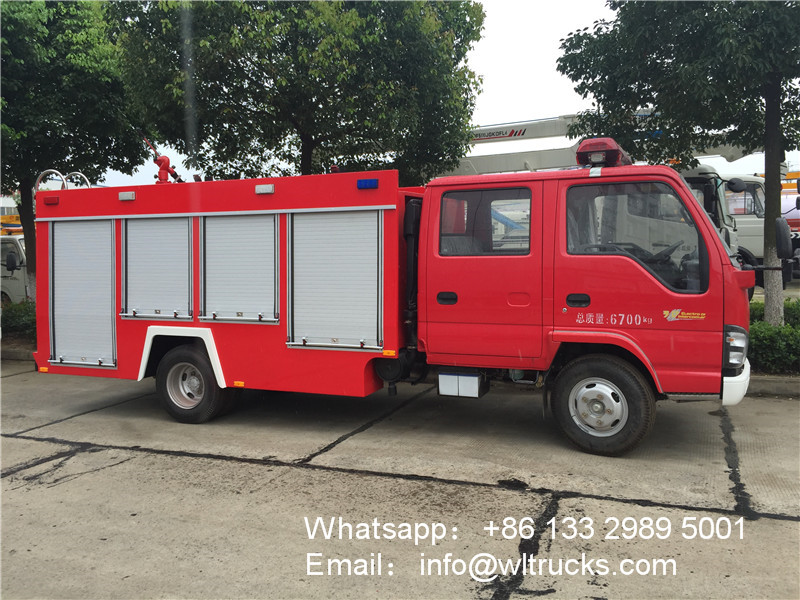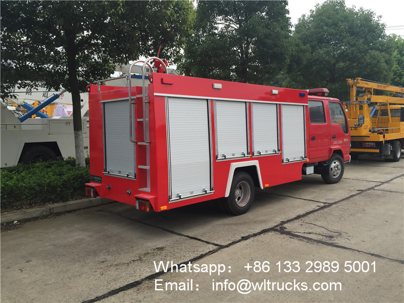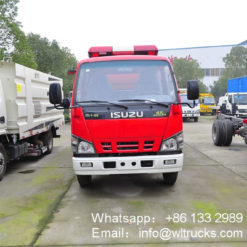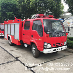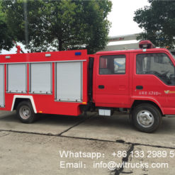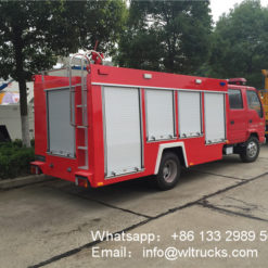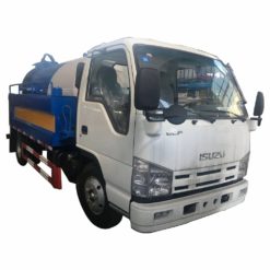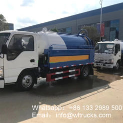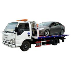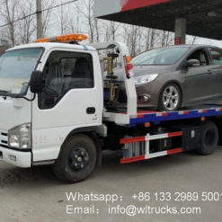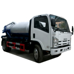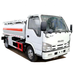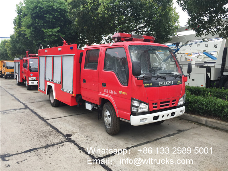
Product Specifications:
| Chassis model | QL1070A5HWY | engine model | Isuzu 130hp/96KW |
| Outside dimensions | 6360×2000×2740mm | Wheelbase | 3360mm |
| Carrier volume | 1980~2500L | Emission Standards | Country Five (Country V) |
| Fire Pump | CB10/20 | Fire cannon | PS20W |
| Fire pump rated flow | 20L/s 1.0MPa | Environmental protection/exemption | There is environmental protection / declaration |
| Rated flow of fire monitor | 20L/s 1.0MPa | Fire gun range | Water ≥48m |
| Special function | Liquid tank | Carrier volume | 4 cubic meters (announcement 3.38 square meters) | |
| Material | Carbon steel ( stainless steel or PP material can be selected as required ) | |||
| Tank fixing | Flexible connection with chassis frame | |||
| Manhole | 1 DN460 manhole with quick lock/open device | |||
| Water inlet | There is a DN65 interface on the left and right sides of the water tank | |||
| Inlet and outlet | 1 water tank to the water inlet pipe of the pump, DN100 valve, manual control 1 water pump to the water tank filling pipe, DN65 valve, manual control |
|||
| Drain | 1 DN40 water tank to put the remaining water port, with manual control of ball valve | |||
| Overflow | 1 DN65 overflow port | |||
| Fire Pump | model | CB10/30 type low-pressure vehicle fire pump | ||
| form | Atmospheric centrifugal | |||
| Installation location | Rear | |||
| flow | 30L/s @1.0MPa | |||
| Outlet pressure | 1.0MPa | |||
| Maximum suction depth | 7m | |||
| Water diversion device | Built-in sliding vane pump | |||
| Diversion time | Maximum suction depth≤35s | |||
| Fire cannon | model | PS30W | ||
| flow | 30L/s | |||
| Rotation angle | 360° horizontal rotation | |||
| Range | ≥55m | |||
| Maximum elevation/depression angle | Elevation angle ≥+60° | Depression angle≤-15° | ||
| Power take-off and transmission system | structure type | Sandwich mechanical transmission | ||
| Clutch method | Hand control | |||
| Lubrication method | Splash lubrication | |||
| Transmission system | Cross shaft universal joint drive shaft | |||
| Pipeline system | Pipe material | High-quality seamless steel pipe | ||
| Suction pipe | There is a DN100 suction port on the back side of the pump room | |||
| Water injection line | There is a DN65 water injection port on the left and right sides of the water tank, and a DN65 water pump is installed in the pump room to inject water into the tank |
|||
| Outlet pipe | There is a DN80 water outlet on the left and right sides of the pump room, with a shut-off valve and a cover | |||
| Cooling water pipeline | Cooling water pipeline and control valve with cooling power take-off | |||
| Electrical Equipment | Fireplace lighting | 1 35W fire searchlight installed at the rear | ||
| Strobe light | Install red and blue strobe lights on both sides of the body | |||
| Warning device | Install a long row of red warning lights on the top of the cab | |||
| Siren | The control box is in front of the driver’s cab | |||
| Auxiliary lighting | Firemen’s room, pump room and equipment box are equipped with lights, and the control dashboard is equipped with bright and indicator lights | |||
| Additional electrical | Set up an independent circuit | |||
| Ladder and handle | Ladder | Aluminum alloy two-section flip ladder, when used, it should not exceed 450mm from the ground, | ||
| Get on the car | Adopt anti-skid round steel pipe with groove on the surface, sprayed on the surface | |||
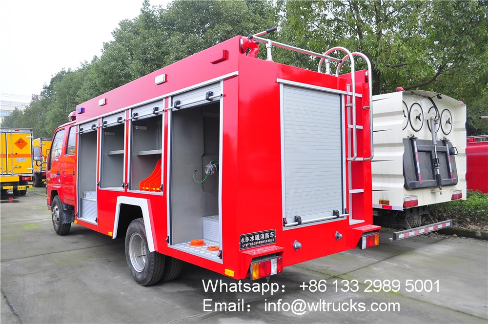
| Equipment box and pump room | structure | The main frame structure is welded with high-quality square tube, and the outer decorative plate is welded with carbon steel plate. | ||
| Equipment box | The equipment box is located at the rear of the passenger compartment. The aluminum alloy rolling doors on both sides are equipped with lighting lamps. The equipment room is equipped with storage boxes according to needs. | |||
| Pump room | The pump room is located at the rear of the vehicle, with aluminum alloy rolling doors on both sides and the back, with lights inside, and some common equipment can be placed on both sides of the pump room | |||
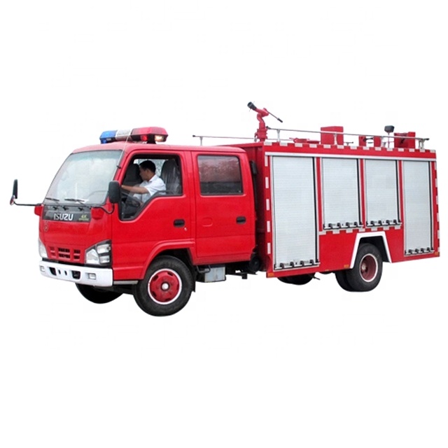
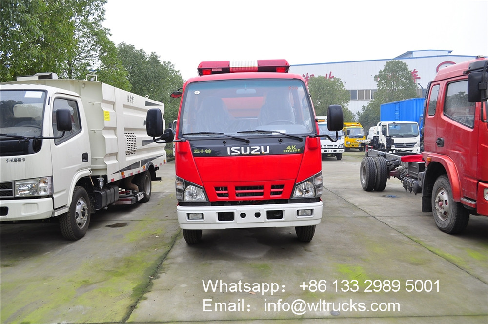
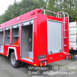
ISUZU 600P 5 ton fire truck detail structure diagram:
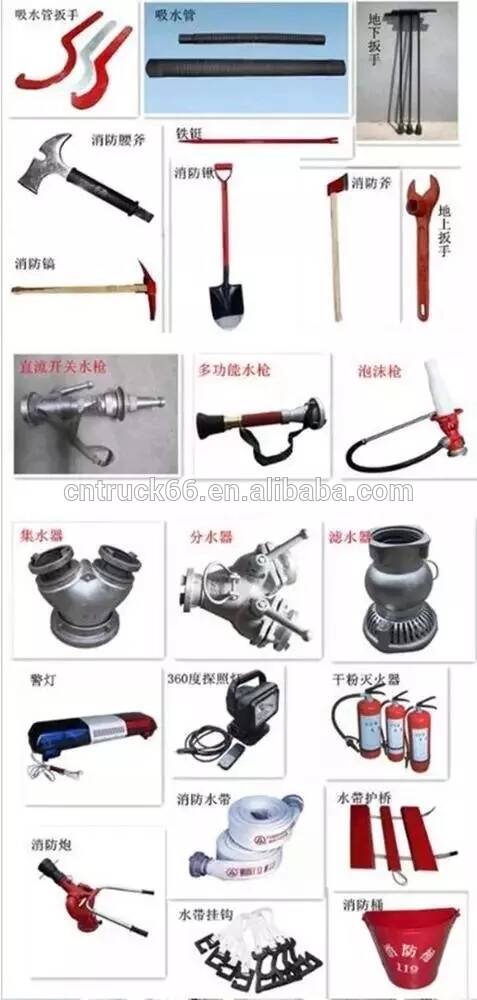
Fire equipment table:
| Serial number | name | specification | Quantity | unit | Remarks |
| 1 | straw | KD100×2 meters | 4 | root | Threaded |
| 2 | Water filter | FLF100 | 1 | Piece | Threaded |
| 3 | Trap | FII80/65×3-1.6 | 1 | Piece | Internal button |
| 4 | Water trap | JII125/65×2-1.0 | 1 | Piece | Internal button |
| 5 | Hose | 13-65-20 | 8 | plate | Low pressure; |
| 6 | Reducing interface | KJ65/80 | 2 | Piece | Internal button |
| 7 | Water-retaining cloth | DT-SB | 4 | Piece | Internal button |
| 8 | Hose hook | 4 | Piece | ||
| 9 | Ground fire hydrant wrench | QT-DS1; length 400 | 1 | Piece | |
| 10 | Underground hydrant wrench | Long 860 | 1 | Piece | |
| 11 | Suction pipe wrench | FS100 | 2 | Piece | |
| 12 | DC switch water gun | QZG3.5/7.5; 65 | 1 | support | Low pressure; |
| 13 | DC Flowering Water Gun | QZK3.5/7.5; 65 | 1 | support | Low pressure; |
| 14 | Fire bucket | 1 | Pc | ||
| 15 | Fire extinguisher | 3KG | 1 | With | |
| 16 | Fire waist axe | Length 390; GF-285 | 1 | Piece | |
| 17 | Rubber hammer | 1 | Piece | ||
| 18 | Rechargeable portable lighting | 1 | Piece |
Optional fire equipment table:
| Serial number | name | specification | Quantity | unit | Remarks |
| 1 | Automatic charging device | 12V | 1 | set | |
| 2 | Air backrest | 3 | set | ||
| 3 | Air breathing apparatus | Number of members | set | ||
| 4 | Hose bridge | rubber | 2 | vice | |
| 5 | Telescopic ladder | 1 | vice | ||
| 6 | Hand lift the pump | 1 | station | ||
| 7 | Breaking tools | 1 | set | ||
| 8 | Other fire equipment |

